
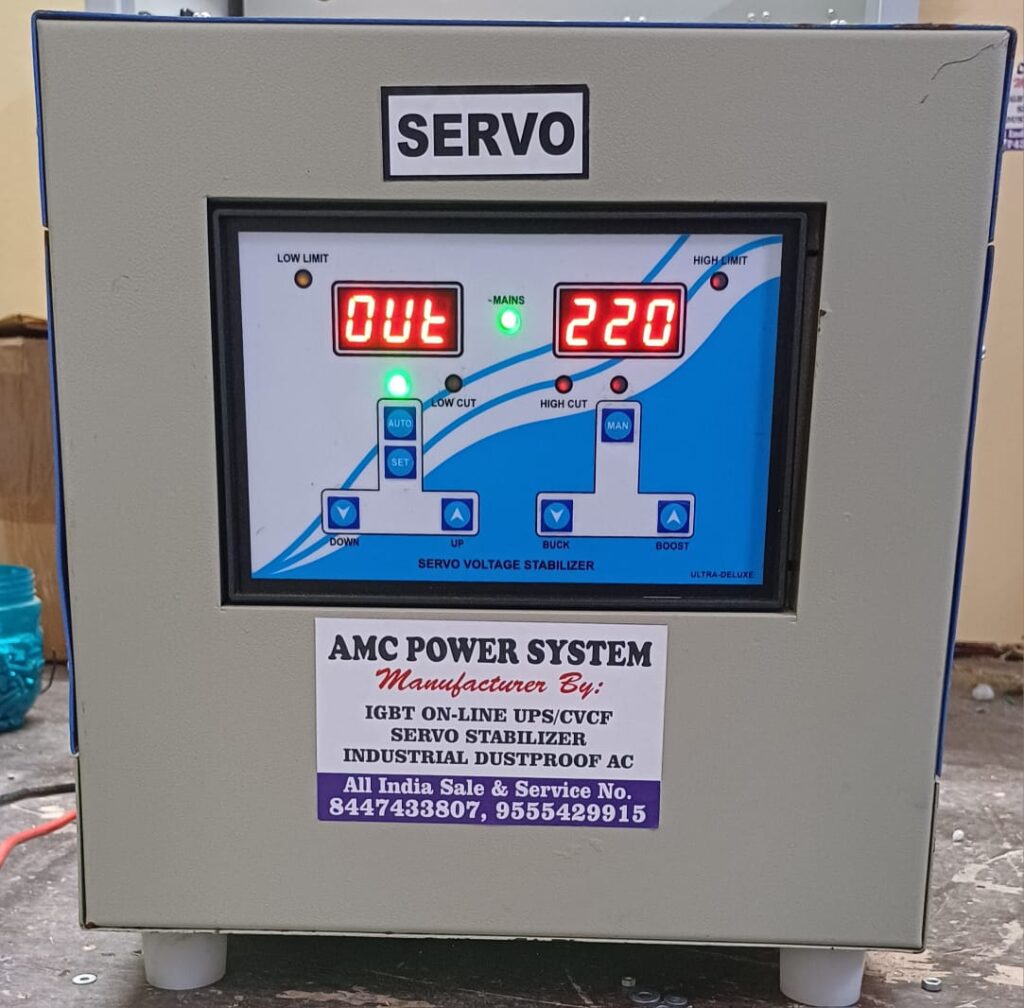
Online UPS (0.5KVA – 50 KVA)
Isolation Transformer
The Isolation Transformer at the output provides galvanic isolation. A UPS without isolation transformer at its output may cause danger to the connected loads in case there occurs a short-circuit in the IGBT blocks of the inverter unit. In that case there is a high probability that the connected loads will be burnt due to high DC voltage.
Another advantage of the galvanic isolation transformer is that it eliminates the peaks (electrical noise or instant peaks) that might appear at the phase, neutral or earth line. For example, in a rainy day if there is lightning at the input, the electrical noise will not be able to pass through the output voltage. As a result the load remain safe.
Power Factor Correction (Optional)
Power Factor Correction unit is available at the input stage of AMC 3 Phase UPS System. While the input power factor is around 0.8 in a normal device without PFC unit. The nearer the power factor to 1, the less electric bill is paid for the reactive power used. At the same time the system efficiency is enhanced and less current is drawn at the UPS input. As the input current is less, you would be benefitted while purchasing a generator with low current rating.
Another advantage of using a UPS with PFC unit is that it does not distort the mains supply. As a result the other electronic devices connected to the mains run safely without any interruption.
Eco-Mode (Optional)
Eco-mode is a low cost UPS operational mode, which provides high efficiency (97%) with respect to the user electric bill. If the bypass exists in the desired voltage range and the harmonic distortion is not so high, the loads can be fed from bypass instead of from inverter output. As soon as the bypass failure occurs, without any interruption the inverter output starts feeding the load. The user can also manually adjust the UPS to either Normal or Eco-mode.
IGBT & PWM Technology
A widely used and developed semiconductor, IGBT (INSULATED GATE BIPOLAR TRANSISTOR), are used in the inverter part of the UPS. With Sinusoidal Pulse Width Modulation Technique, maximum operational efficiency is obtained and thus even the non-linear loads are fed with precise sinusoidal signals.
Parallel Configuration (Optional)
Parallel configuration is a system, which ensures more sensitive and reliable operation of the UPS to continue feeding the loads. For example, in a parallel configuration even if one of the UPS goes out of order, the other units still operate and thus ensure a continuous feeding of the load without any interruption. In this way, by this system n+1 units can be connected in parallel and thus altogether increase the total capacity of the system. In this way, whenever necessary, the user can add an extra unit to feed a larger load system.
Hot Stand-by Configuration
- Feed one (priority) or two (priority & normal) load banks depending on the application need.
- Increase the reliability of the priority load.
- Increase the maintainability.
- Easy connections.
- Can be implemented in the existing installation regardless of the UPS size, the generation (of device, technology or control mechanism) and the manufacturer.
Technical Specification
AC Input Voltage
- Single Phase: 230V ± 20% / 2Wire
- Wide Input Window: 120V – 280V
- Input Power factor: > 0.9
- Power Factor Correction: > 0.99 (Optional)
Input Frequency
- 45 Hz – 55 Hz
- Can also work on Generators
DC Output (Rectifier)
| System Rating | Output Voltage (Nominal) |
|---|---|
| 1 KVA – 15 KVA | 24V / 36V / 48V / 72V / 96V / 120V / 180V / 220V / 240V |
| 20 KVA – 50 KVA | 96V / 120V / 180V / 220V / 240V |
Output voltage depends on the DC voltage range as selected by customer
Output Parameters
| # | Parameter | Values |
|---|---|---|
| 1 | Output Voltage (Nominal) | As per load requirement & Output level selection |
| 2 | Voltage Regulation | ± 1% |
| 3 | Output Frequency | 50 Hz ± 0.01% (Optional: 60 Hz) |
| 4 | Frequency Stability | Crystal controlled ± 0.01% |
| 5 | Output Waveform | Pure Sine Wave |
| 6 | Waveform Distortion (THD) | < 3% on resistive load |
| 7 | Crest Factor | > 3:1 |
| 8 | Inverter Efficiency | > 90% |
| 9 | Power Factor | 0.8 lag to 1.0 lead |
| 10 | Overload Capacity | 110% for 10 mins, 120% for 1 min, 150% for 10 sec |
| 11 | Protections | Input low/high cut, output over/under voltage, overload, short-circuit |
| 12 | Indications | LCD for Voltage, Frequency, Load, Battery, etc. |
| 13 | Alarm | Audio alarm for fault, low battery, overload |
SELF & DIAGNOSTIC FEATURES
- Input Voltage / Output Voltage
- Output Frequency / Output Current
- Output Load Level / Battery Voltage
- Battery Charging Current
INDICATIONS
| LED Indications | System ON | Mains ON | Battery ON | Load ON | Load Level |
|---|
AMBIENT CONDITIONS
- Operating Temperature: 0°–50°C
- Relative Humidity: 0–95% (Non-condensing)
- Cooling: Forced Air Cooling
METERING
Digital LCD Display – Input / Output Frequency, Voltage, Load, Battery etc.
OPTIONAL FEATURES
- Static Bypass
- RS232 / RS485 Interface
- Alarm Extension Panel
- Remote Monitoring System